Portable Large Scale Laser Tracker | High-Precision 3D Industrial Measurement System


Precision Metrology for Aerospace, Automotive & Heavy Industry
Our portable large scale laser tracker delivers high-accuracy 3D coordinate measurement for demanding industrial applications. Engineered as an optical CMM (coordinate measuring machine), this laser tracker system enables precise robot calibration, large workpiece alignment, and real-time quality inspection across aerospace, automotive manufacturing, rail transit, and heavy machinery sectors.
Why Choose Our Laser Tracker?
High Accuracy: Achieve micrometer-level precision
Portable Design: Easy to transport and set up on the factory floor or outdoor job sites.
Versatile Applications: Ideal for reverse engineering, assembly verification, and machine alignment.
Trusted Manufacturer: Factory-direct pricing with OEM support and global shipping.
Optimize your industrial metrology workflow with a solution trusted by leading laser tracker suppliers. Whether you need a portable laser tracker for sale or a custom industrial laser tracker system, we provide reliable performance at competitive laser tracker cost.
Contact us today for a quote or technical consultation.
Product Introduction
The laser tracker is primarily used for precise measurement of three-dimensional coordinates in large-scale spatial environments (up to 100 meters). It integrates laser interferometric ranging technology, photoelectric detection technology, precision mechanical technology, computer and control technology, and modern numerical calculation theory. It is the most accurate and important industrial scientific instrument for large-scale spatial measurement, and the only high-performance photoelectric instrument simultaneously possessing μm-level accuracy and a 100-meter working space. The laser tracker can be used for applications such as dimensional measurement, installation, positioning, calibration, and reverse engineering, making it a powerful metrology and testing tool.
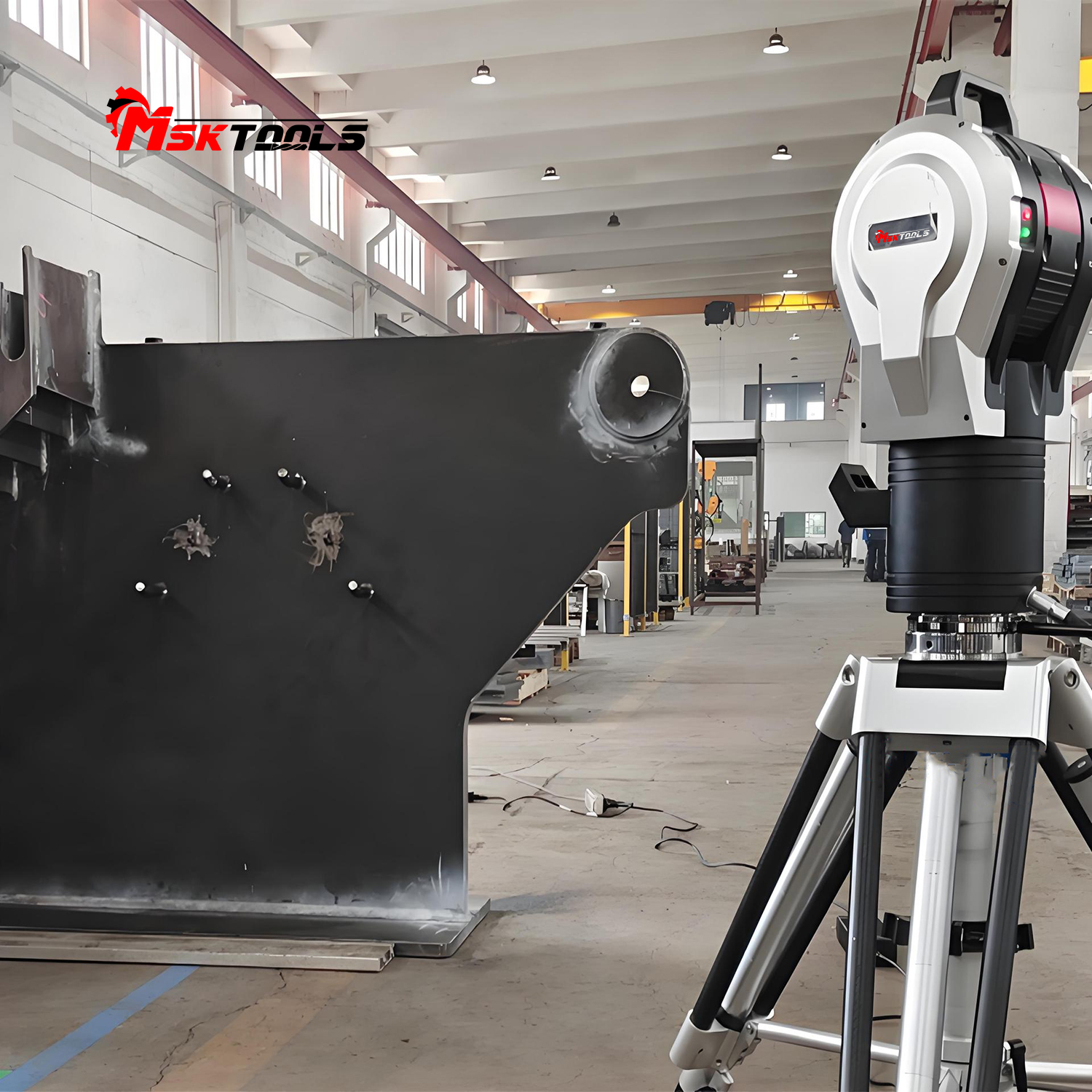
The GTS laser tracker system consists of a computer, a tracking measurement station, and a target mirror. It combines angle and distance measurements in both horizontal and vertical directions to form a spherical coordinate measurement system. The target mirror acquires measurement point information for spatial geometric elements, and 3D data analysis software performs analysis and calculations on the dimensions, dimensional tolerances, geometric tolerances, and spatial surfaces and curves of these elements.
GTS laser trackers can be widely used in various large-scale spatial precision measurement fields, such as measuring the accuracy of aircraft parts and assembly in the aerospace industry; measuring the flatness, straightness, and cylindricity of machine tools in the machine tool industry; online measurement of vehicle models in automobile manufacturing; and precise calibration of the position of moving robots in high-end manufacturing. In addition, laser trackers can also be widely used in advanced manufacturing fields such as shipbuilding, rail transportation, and nuclear power.
Features
1. Integrated Control Unit Design: A powerful CPU and compact control unit are integrated into the laser tracking head. This integrated design significantly reduces the number of connecting cables and carrying cases, facilitating rapid on-site installation.
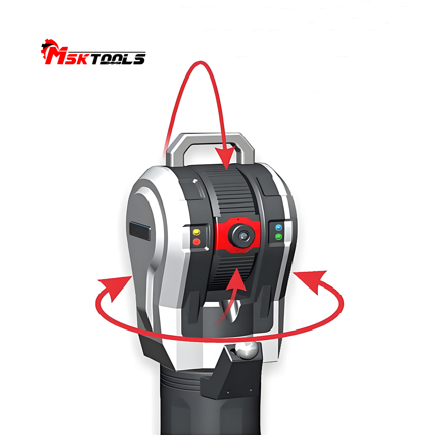
2. Automatic Target Ball Locking Technology: When the light source is interrupted, the target locking camera automatically searches for the target ball within a small area, resumes light transmission, and automatically locks onto the target ball. The entire process requires no manual operation, improving measurement efficiency.
3. HiADM Ranging Technology: The HiADM technology combines laser absolute ranging (ADM) and laser interferometric ranging (IFM) with the high dynamic speed of laser interferometric ranging, ensuring excellent measurement accuracy and enabling light obstruction recovery.
4. Integrated Weather Station: The integrated environmental weather station automatically monitors and updates environmental meteorological parameters, compensating in real-time for the effects of temperature, air pressure, and humidity on the refractive index of the laser in the air, ensuring measurement accuracy. 5. MultiComm Communication: The device can communicate with the computer via various methods, including hardware triggering, wired network, or wireless WIFI, facilitating on-site use in secure workshops. The maximum measurement data output speed is 1000 points/second.
6. Encoder Self-Calibration: The grating encoder self-calibration technology allows the system to perform encoder calibration independently without external auxiliary equipment. On-site calibration is particularly convenient when measurement environmental conditions and instrument status change.
7. Portable Transportation: The integrated main unit design of the laser tracking head and the integrated accessory transport case make the entire transport system compact, lightweight, and highly user-friendly, facilitating transport between different work locations.
8. Sealed Protection Design: IP53 protection rating ensures the main unit is protected from dust and other contaminants, making it highly adaptable to various environments.
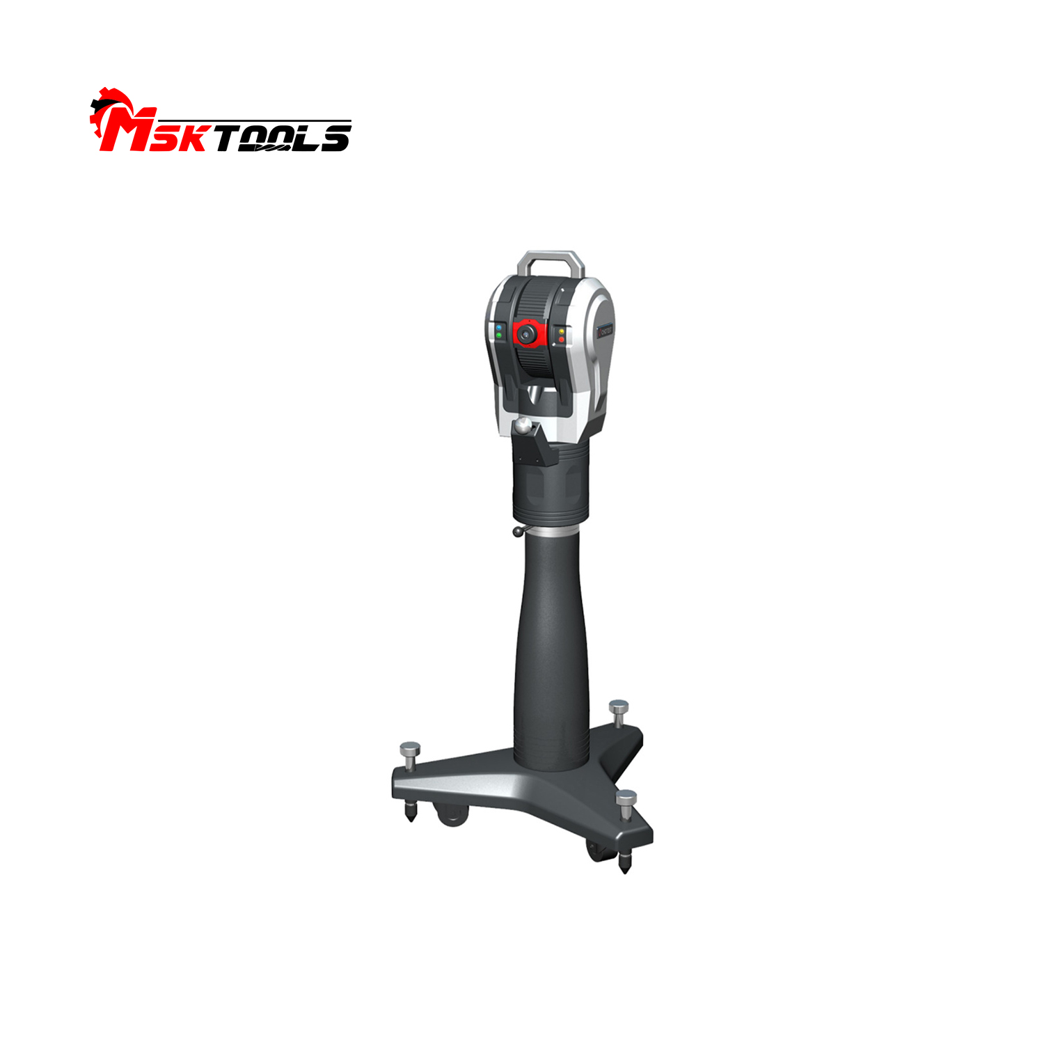
9. Stable Tripod: The stable and convenient tripod and chassis design ensures stable ground measurement conditions. The clever lifting mechanism allows for effortless operation, and the sturdy tripod support system prevents accuracy loss due to environmental vibrations.
III. Technical Specifications
1. Main Unit Specifications
| Project | GTS3300 | |
| Basic Specifications | Tracking head dimensions | 220x280x495 mm |
| Tracking head weight | 21.0Kg | |
| Controller | Integrated | |
| Laser*1 | 633nm, ImW/CW|Class 2 | |
| Protection class | IP53 | |
| Measurement range | Maximum measurement radius | 30 meters |
| Horizontal direction | ±360° | |
| Vertical direction | -145°~+145° | |
| Measurement accuracy *2 | Angle accuracy*3 | 15μm-6μm/m |
| Interferometric ranging accuracy | 0.5μm/m | |
| Absolute ranging accuracy | 10μm (full range) | |
| Level accuracy | 2.0" | |
| Target recognition | Target locking distance | 30m |
| Camera and field of view | 1.3MP|10° FOV | |
| Tracking performance | Data output speed | 1000 points/second |
| Maximum tracking speed* | 3 meters/second | |
| Weather station accuracy | Air temperature sensor | 0.1°C (0-40°C) |
| Air humidity sensor | 6% (0-95%) | |
| Air pressure sensor | 0.1kPa | |
| Target ball specifications | Target diameter | 0.5 inches~1.5 inches |
| Sphere center accuracy* | 3μm~7.5μm | |
| Communication Interface | Cable interface | TCP/IP (Cat5) |
| Wireless interface | WLAN (IEEE) 802.11N) | |
| Environmental Requirements | Operating temperature | 0°C~40°C |
| Altitude | -500~+3500 meters | |
| Relative humidity | 0~95%, non-condensing | |
| Power Supply | Power supply type | AC |
| Operating power supply | 220+10%VAC, 50/60Hz, 4A, 220W | |
1) Complies with IEC 60825-1 (2014-5) and meets radiation performance standards.
2) The accuracy specification is the maximum permissible error (MPE), using standard 1.5” SMR, excluding the influence of air temperature variations.
3) Angular lateral error conforms to ISO 10360-10-2016; double-sided measurement position error (MPE) meets 30μm ± 12μm/m.
4) Complies with JJF 1242-2010 Calibration Specification for Laser Tracking Three-Dimensional Coordinate Measurement Systems.
5) Target sphere diameter and center accuracy specifications are optional.
2. Product Configuration List
| Serial Number | Name | Describe | |
| 1 | Host | Tracking head | One unit, capable of both absolute ranging and interferometric ranging (depending on the model). |
| 2 | Portable carbon fiber tripod | 1 unit, FT-1100-L, Portable Carbon Fiber Tripod
1) Carbon fiber legs, extendable; 2) Integrated bubble level; 3) Height adjustment range: 63-110cm; |
|
| 3 | Carbon fiber tripod transport case | One unit with handle and wheels for mounting a portable carbon fiber tripod. | |
| 4 | RJ-45 5m network cable | One piece for connecting the tracking head and computer. | |
| 5 | Optical cleaning kit | One set for cleaning the light-emitting aperture lens, etc | |
| 6 | Data concentrator | One set for environmental parameter acquisition and instrument data exchange | |
| 7 | Main unit transport box | 1 unit, for holding the tracking probe, etc | |
| 8 | Calibration Tools | Calibration rod | 1 unit, with calibration box, used as a length reference for instrument accuracy verification |
| 9 | Calibration tripod | 1 unit, used for full-space calibration and testing of the instrument | |
| 10 | Notebook | One set, including supporting software for analysis and calculation. CPU: I7-10th generation, Memory: ≥16G | |
| 11 | 1.5” target ball reflector | One 1.5” target sphere reflector Receiving angle range: ±25° Weight: 170g Optical center error: ±3µm Sphericity: 1.5µm Radius: 19.05mm ±0.002mm |
|
| 12 | Reflective sphere base | 1.5” Pin-type Target Mount | 1. Target diameter 25.4mm, offset 25mm, rod diameter 8mm, stainless steel. For hole position measurement |
| 13 | 1.5” Planar Target Mount | 1. Target diameter 40.64mm, offset 25mm, stainless steel. For plane measurement | |
| 14 | 1.5” Edge Target Mount | 1. Target diameter 40.64mm, offset 25mm, stainless steel. For edge measurement | |
| 15 | 1.5” Transfer Target Mount | 6. Target diameter 40.64mm, offset 25mm, aluminum, magnetic base | |
| 16 | Space Measurement Software | Dongle | 1 unit |
| 17 | Software CD | 1 set, Spatial Master (64-bit) | |
| 18 | Other | Instruction manual | 1 book |
| 19 | Certificate of conformity | 1 copy | |
| 20 | Warranty card | 1 copy | |
| 21 | Heavy-duty tripod | 1 set | |
| 22 | Third-party space measurement software | 1 set, Spatial Analyze (Version Negotiation Selection) | |
| 23 | 0.5" target sphere reflector | 1 piece, receiving angle range: ±25° Weight: 6g Optical center error: ±3µm Sphericity: 1.5µm Radius: 6.35mm ±0.002mm |
|
| 24 | Reflective sphere base | 0.5” pin target mount | 1 target, 12.7mm diameter, 10mm offset, 8mm rod diameter, stainless steel |
| 25 | 0.5” planar target mount | 1 target, 12.7mm diameter, 10mm offset, stainless steel | |
| 26 | 0.5” edge target mount | 1 target, 12.7mm diameter, 10mm offset, stainless steel | |
| 27 | Wireless remote control device | 1 set, supporting remote control of instrument data acquisition, 2.4GHz | |
| 28 | Main unit calibration certificate | 1 copy | |
About Us
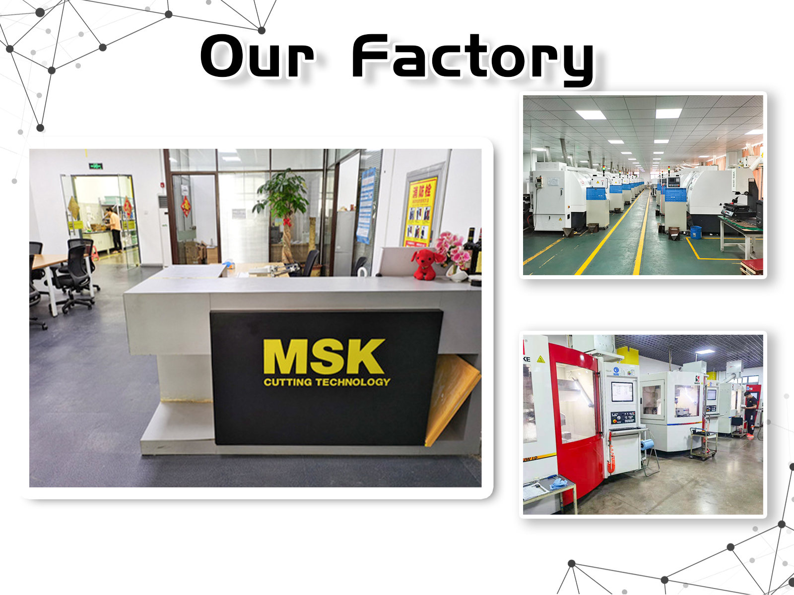
Factory Profile
Why Choose Us

FAQ
Q1: Who are we?
A1: Founded in 2015, MSK (Tianjin) Cutting Technology CO.Ltd has grown continuously and passed Rheinland ISO 9001
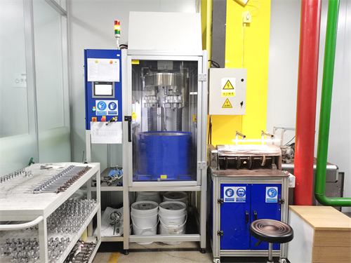
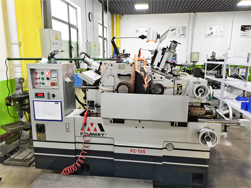
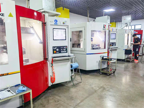
authentication.With German SACCKE high-end five-axis grinding centers, German ZOLLER six-axis tool inspection center, Taiwan PALMARY machine and other international advanced manufacturing equipment, we are committed to producing high-end,professional and efficient CNC tool.
Q2: Are you trading company or manufacturer?
A2: We are the factory of carbide tools.
Q3: Can you send products to our Forwarder in China?
A3: Yes,if you have Forwarder in China,we will glad to send products to him/her.
Q4: What terms of payment are acceptable?
A4: Normally we accept T/T.
Q5: Do you accept OEM orders?
A5: Yes, OEM and customization are available, and we also provide label printing service.
Q6: Why should you choose us?
A6:1) Cost control - purchasing high-quality products at an appropriate price.
2) Quick response - within 48 hours, professional personnel will provide you with a quote and address your concerns.
3) High quality - The company always proves with sincere intention that the products it provides are 100% high-quality.
4) After sales service and technical guidance - The company provides after-sales service and technical guidance according to customer requirements and needs.


