In the world of CNC machining, the reliability of your tool holding system directly impacts part quality, tool life, and operational safety. At the heart of this system lies the spindle drawbar force—the clamping force that holds the tool holder in the spindle taper. Whether you’re running a high-speed drill/tap center with BT30 tooling, a versatile BT40 machining center, or a heavy-duty BT50 machine, accurately measuring this force is critical.
This comprehensive guide explains everything you need to know about BT spindle drawbar force gauges, why you should monitor BT30 BT40 BT50 spindle clamp force, and how a spindle tension meter helps you prevent costly downtime.
What Is Spindle Drawbar Force and Why Does It Matter?
The spindle drawbar force is the axial pull exerted by the drawbar mechanism (typically a set of Belleville springs or a hydraulic system) onto the pull stud of a tool holder. This force clamps the tool holder tightly against the spindle taper, ensuring:
- Rigidity during heavy cutting – Prevents micro-movement that leads to chatter and poor surface finish.
- Reliable tool retention – Eliminates the risk of tool pullout, especially in high-speed or high-torque operations.
- Protection of spindle and tooling – Correct force avoids excessive wear on the gripper fingers and spindle taper.
If the drawbar force drops below the recommended level, you may experience tool slippage, increased runout, or even catastrophic tool ejection. Conversely, too much force can overstress the gripper mechanism and shorten its life. Regular measurement with a dedicated spindle drawbar force gauge is the only way to verify that your machine is operating within safe parameters.
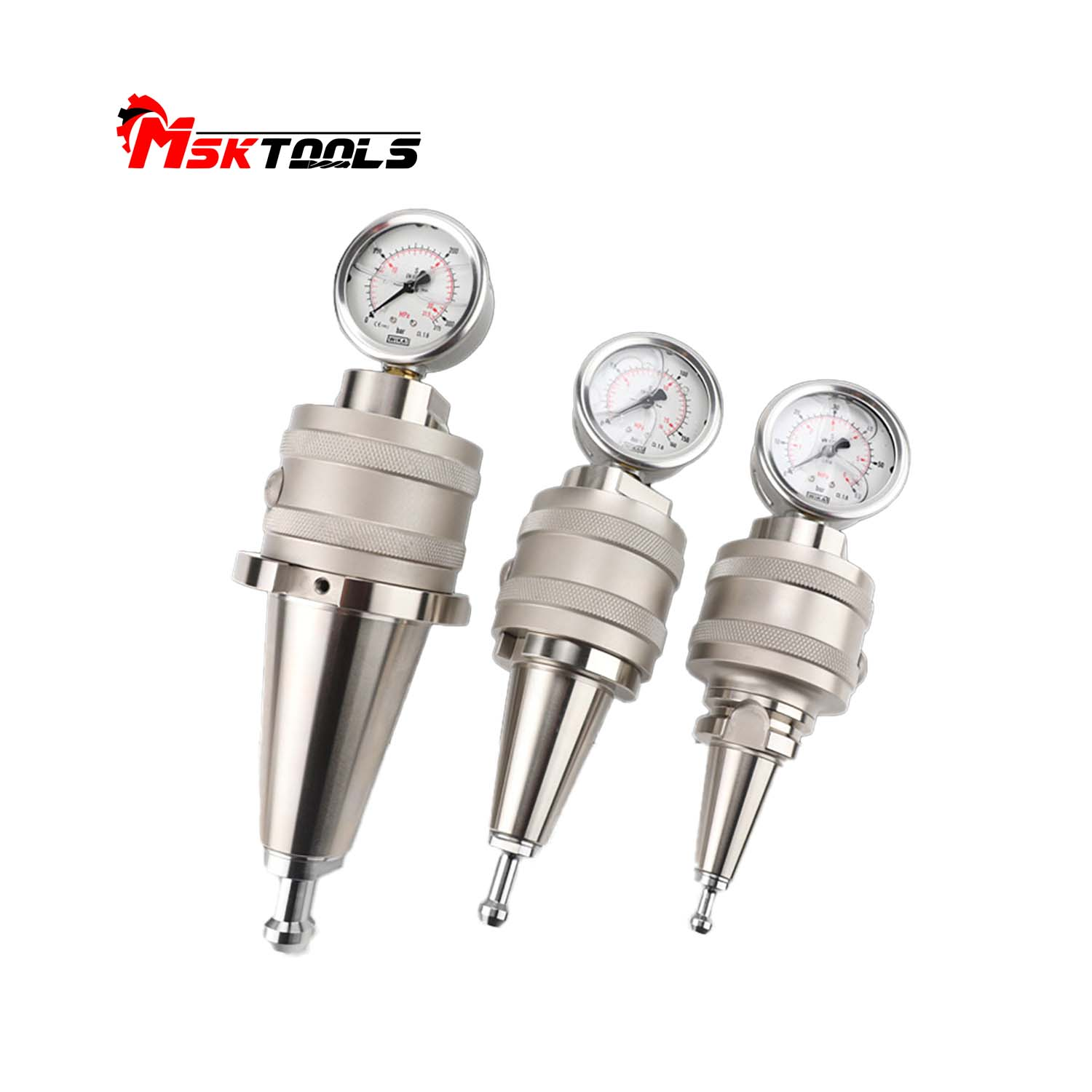
Recommended Clamp Force Ranges for BT30, BT40 & BT50
Different spindle tapers and machine types demand different clamp forces. While exact values depend on the machine builder’s specifications, the following general guidelines are widely accepted in the industry:
| Product Model | Measurement range | Package weight |
| BT30 | 0-60Kg/cm² | 4.2Kg |
| BT40 | 0-150Kg/cm² | 4.3Kg |
| BT50 | 0-350Kg/cm² | 6.7Kg |
Always refer to your machine’s manual for the exact values.
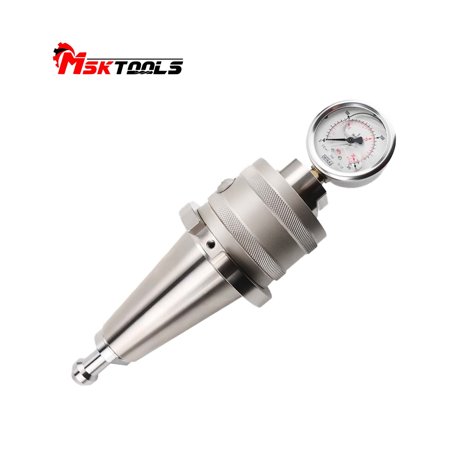
How a Spindle Tension Meter Works
A spindle tension meter (also called a drawbar force gauge) typically consists of a precision load cell housed inside a dummy tool holder that matches your machine’s taper (e.g., BT30, BT40, or BT50). When you insert the gauge into the spindle and actuate the tool change cycle, the drawbar pulls on the integrated pull stud. The sensor measures the force, and the result is displayed on a digital indicator or stored for later analysis.
Key Features to Look For in a Quality Gauge:
- Interchangeable adapters – One gauge body that accepts different taper heads (BT30, BT40, BT50, etc.) saves cost and storage space.
- High accuracy – Look for ±1% or better full-scale accuracy to detect subtle changes.
- Peak hold function – Captures the maximum force during the clamping cycle.
- Data logging – Some advanced models store measurements for trend analysis and predictive maintenance.
- Easy-to-read display – Backlit digital screens make reading in a busy shop floor simple.
Step-by-Step: Measuring Spindle Clamp Force
Follow these steps to get reliable, repeatable measurements:
- Clean the spindle taper – Any chips, coolant residue, or grease will affect the reading. Wipe the taper and the gauge’s taper with a clean, lint-free cloth.
- Select the correct adapter – Attach the BT30, BT40, or BT50 head to your spindle drawbar force gauge.
- Insert the gauge – Carefully place the gauge into the spindle, ensuring it engages the drive keys and seats properly.
- Initiate the clamping cycle – Use the machine’s manual or automatic tool change command to clamp the gauge.
- Read the force – Note the value on the display. It’s good practice to take measurements at several spindle orientations (e.g., 0°, 90°, 180°, 270°) to check for inconsistencies.
- Release and repeat – Perform at least three measurements and average the results.
- Record the data – Keep a log to track trends over time. A gradual decline may indicate spring fatigue.
Choosing the Right BT Spindle Drawbar Force Gauge
When selecting a gauge for your shop, consider:
- Taper compatibility – Do you need a dedicated unit for one taper, or a multi-taper system?
- Force range – Ensure the gauge can cover the forces of your largest spindle.
- Build quality – Look for hardened steel construction to withstand repeated use.
- Display type – Digital gauges with intuitive interfaces reduce operator error.
- Calibration – Choose a gauge that can be easily calibrated and comes with a traceable certificate.
Investing in a reliable spindle tension meter pays for itself by preventing crashes, reducing scrap, and extending spindle life.
Integrating Drawbar Force Testing into Your Maintenance Routine
To maximize uptime, incorporate drawbar force checks into your regular preventive maintenance schedule. Many shops perform tests:
- Monthly for high-production machines.
- Quarterly for standard machining centers.
- After any spindle repair or reconditioning.
- When tool pullout or chatter issues arise.
By monitoring BT30 BT40 BT50 spindle clamp force, you can detect problems early and schedule repairs during planned downtime instead of emergency shutdowns.
Conclusion
Accurate measurement of spindle drawbar force is not optional—it’s essential for safe, efficient, and profitable machining. Whether you work with BT30, BT40, or BT50 spindles, a high-quality BT spindle drawbar force gauge gives you the data you need to keep your machines running at peak performance.
Ready to take control of your spindle health? Explore our range of precision spindle tension meters with interchangeable heads for all common tapers. Contact us today for expert advice and a quote tailored to your shop’s needs.
Post time: Mar-10-2026


